Beta Address: http://blish.org/sdrdxdoc/digimodes.html
5.15.12 - Digital Modes
There are various interesting digital data modes on the air; Amateur radio operators use quite a few of them. If you'd like to use SdrDx to receive some of these under OS X, I suggest you obtain SoundFlower, which is a free program that lets one program "see" the audio produced by another, and fldigi, a program that takes the received audio and converts it into images, text and so forth.
To use SoundFlower to route the output of SdrDx to fldigi:
Once Soundflower is installed, start both SdrDx and fldigi. Set fldigi to the "native" sound data rate, select Soundflower (2ch) as the fldigi audio input, use the dialog to set the output of SdrDx to Soundflower (2ch), adjust the bandwidth in or to tightly surround the data signal, and enjoy.
I've had excellent results with RTTY, SSTV, FAX, CW, Packet, Olivia, and more.
To use another program, just follow the above steps, but any step done for fldigi is instead done for the other program. It's really just a matter of sample rate (and not all programs let you adjust that) and audio input selection.
If you prefer not to install soundflower, routing the audio outputs of your computer back to the audio inputs will also work, although now hearing the signal may be an issue. An external mixer can help with this.
5.15.12.1 - Carrier Point Readout
The SdrDx demodulator frequency readout indicates the 0-frequency carrier point for the demodulator. For FSK modes such as RTTY and SITOR, and for other modes like CW, in order to get the signal into the part of the passband you want in order to get the particular tone or tone set you want, you have to treat the carrier of the the signal as offset.
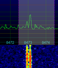
For instance, WLO broadcasts RTTY and SITOR centered about 8,473.000 KHz, using a 170 Hz shift around that center frequency, or another way to look at it is as one shift 85 Hz below that frequency, and one 85 Hz above.
Now, let's say you have your RTTY / SITOR decoder set up to expect tones centered around 1500 Hz. This means that in order to get those tones to land in the desired location in the passband in , you have to tune 1.500 KHz above the signal; so in mode, you'd actually tune to 8,474.500 KHz, a 1.500 KHz offset. Now WLO's signal demodulates into frequency-shifted audio around 1500 Hz, with shifts at 1585 Hz and 1415 Hz.
In such a circumstance, keeping in mind you are working with a lower sideband demodulator mode, you'd want to adjust the demodulator passband so that it begins a bit below -1585 Hz, and ends a bit above -1415 Hz.
If you set the demodulator symmetrically, that is, the same amount above and below the -1500 Hz carrier point (for instance, -1250 Hz and -1750 Hz) then SdrDx's demodulator center point readout, just below the two main frequency readouts, will indicate the center of the demodulator - 8,473.000 KHz, so you have an actual readout of the broadcast center handy. Keep in mind achieving the center readout of the signal depends upon symmetry: You must have the demodulator passband equally offset on both sides.
5.15.12.2 - Direct setting of carrier offset
To set carrier offsets for FSK and CW modes that will be obeyed by the TCP command set and the ⇑ ENTER command, →Right-click , , , and
The demodulator memories through store and recall bandwidths, but they also the offsets along with the bandwidths for , , , and
So, for instance, if you want to look for the beacons on 14100, press ⇑ ENTER and type 14100c which will put you right on target (as long as you have your CWL demodulator bounds set to correspond with the →Right-click programmed offset, of course.)
5.15.12.3 - Direct setting of center offset
To set an offset for the center frequency that will be obeyed by the TCP command set and the ⇑ ENTER command, →Right-click
5.15.12.4 - RTTY, NAVTEX-B, and SITOR-B Reception
The Radioteletype ( ) mode of the scope can help in both tuning and determining the shift of received RTTY, SITOR-B and NAVTEX-B signals.
You should use either or to receive these modes. For 170 Hz shift on 20 meters, I have found that setting the scope for a 1500 Hz center frequency and 170 Hz width, using the demodulator mode with a bandwidth of Hi=-1350 and Lo=-1650 works well. These settings provide a 300 Hz bandwidth, which incorporates a safe and suitable margin on each side of the signal to accommodate sidebands generated by baud rates as high as 100. You can go tighter if the baud rate is less than 100. Make sure is off as otherwise it will introduce phase shift and attenuate one of the FSK tones.
To demodulate RTTY entirely within SdrDx, first →Right-click . While there are a number of choices you can make, there are one-click presets for both standard 170 Hz RTTY and for SITOR (which is essentially the same as NAVTEX.) Just press the button. You can use the button to control the text display's behavior with newlines. You will see flash when the RTTY demodulator encounters a framing error (a space where it selected a mark, or vice-versa.) Once you have the settings you want, close the dialog and →Left-click .
The default settings for RTTY are Baudot (actually ITA2) code, 1000 Hz center, 170 Hz shift, 45.45 baud, 1 stop bit, non-inverted, unshift-on-space and unshift-on-error.
The default settings for SITOR-B / NAVTEX-B are CCIR476 code, 1000 Hz center, 170 Hz shift, 100 baud, non-inverted, unshift-on-space and unshift-on-error. Stop bits are set to zero, as they are not used in these modes, which are fully synchronous.
Both RTTY and SITOR-B / NAVTEX-B use encoding whereby there is one set of characters for letters, and another for numbers and other symbols. The codes switch between them using special "shift" characters; it is possible to receive a shift, and then fail to receive the un-shift, leaving the display producing numbers and symbols instead of letters.
 Inverted , when checked, will cause SdrDx to read "1" bits as "0" bits and vice-versa. The effect is the same as if you switched sidebands.
Unshift-on-Error , when checked, will cause SdrDx to automatically shift "down" to the letters mode when a receive framing error is detected for RTTY, or an unrecoverable encoding error is encountered in SITOR-B / NAVTEX reception, or when SYNC is lost.
Unshift-on-Space , when checked, will cause SdrDx to automatically shift "down" to the letters mode when a "space" character is received. This is a very common feature in demodulation, and stations that transmit sequences of numbers separated by spaces almost always shift up, send the numbers, shift down, send a space, shift up, and send the next number, and so on, which makes this feature perform very well indeed.
For these modes, phase and amplitude accuracy are paramount. So in order for most decoders to process them effectively, you need to ensure that all of the following are turned off:
WLO has been known to alternate between RTTY and SITOR-B, so if the signal won't decode, it is being received reasonably well, and you're sure you have your settings and tuning right, try waiting a few minutes. Once you know what RTTY and SITOR sound like, you'll be able to tell by ear which mode the station is broadcasting in.
If you prefer SITOR, essentially the same advice applies — tune SdrDx the same way, set the demodulator up for 1500 Hz center with 300 Hz bandwidth, set the scope for 1500 Hz center, and if the signal won't decode after you hear a SYNC burst, it's probably in RTTY mode, so wait for it to change back to SITOR and send another SYNC burst.
WLO broadcasts from the American south. somewhere near Atlanta, Georgia.
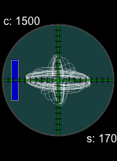
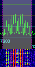
5.15.12.5 - Tuning PSK31
Select next to the auxiliary scope. Right-click it and set the Scope Filter Q to 999. Adjust RTTY Gain to taste. Close the dialog. Using the knobs, set the center frequency to 1085 and the shift to 170. Select . Now set your demodulation edges to 1000 and 1050. (I save this in the bandwidth memory for convenience. That's done by clicking followed by .) Set your demodulation software for 1000 Hz. Find a good PSK31 signal, and tune so that it is visually in the center of the demodulator passband. Finally, adjust CWO so that it demodulates as expected. This procedure sets things up so that tuning PSK31 involves getting a flat loop on the auxiliary scope, and is reliably repeatable as you tune across the band. Turn off all audio filtering as noted above.
5.15.12.6 - CW Reception
First, tune to a frequency where CW signals are normally found, such as around 7010 KHz. Switch SdrDx to receive mode. Then adjust the bandwidth by either dragging the demodulator region's edges or with ( ^ ↑, ^ ↓, ^ →, and ^ ← ) so that the bandwidth is a little bit wider than the CW signals. Now put a CW signal right in the middle of the bandwidth indicator. Finally, adjust CWO (offset) at the bottom of the window so that the tone of the received signal is pleasant for you to listen to.
You now have a real CW chasing radio setup with awesome filtering, excellent impulse response, and terrific fidelity.
5.15.12.7 - SSTV and FAX reception
NOAA 15 APT signal
at 137.620 MHz
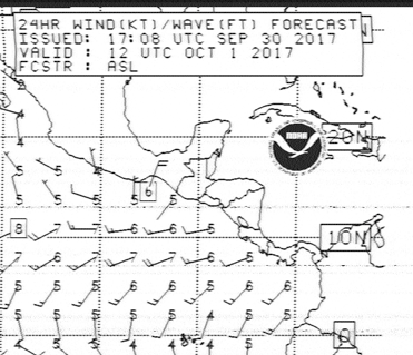
Weather
FAX
In waterfall mode ( ) the scope can help in tuning of received SSTV and FAX signals. Simply →Right-click with the scope bandwidth set to and , and you'll see reference lines at 1200, 1500 and 2300 Hz. Use these to precisely align the signals.
You'll want to use either or to receive SSTV or WEFAX FAX, with bandwidth from about 1000 hz to 2400 hz.
For fax reception from satellite, you use  FM, with bandwidth set to 40 KHz and all audio filtering off in SdrDx. In your receive software, you want 120 LPM, IOC 576, Greyscale, and satellite or APT mode.
5.15.12.8 - DGPS - Differential GPS reception
From 285.000 to 325.000, signals are broadcast that are intended to increase the accuracy of GPS receivers that are specially equipped for reception of stations broadcasting land-based differential correction of the GPS satellite signals. These are called DGPS signals.
The DGPS stations know exactly where they are. They use that knowledge when they listen to the satellite GPS signal, and whatever error between the signal and their already-known actual location they detect, they encode and send out digitally along with an identifier that indicates the location that is being corrected. In turn, differential-enabled GPS receivers listen for these signals, and use the nearest stations to correct the incoming GPS signals to be more accurate.
Here's a quick example of differential correction.
Say you have a DGPS station located on a line which has intervals located from zero to 100; the station is located at exactly position 17 . This station is listening to a GPS satellite that is attempting to tell it where it is. There is a small error; it says the station is located at position 19, which is wrong by 2 , too high. So the DGPS station transmits -2 as the differential error at its location.
Now you have a location device that listens for where it is on that line. It doesn't know where it is, though, it's providing the information based on the satellite data, so when it says the location is 52, it's close, but because satellite location is inherently inexact, it's only close.
Now comes the differential-enabled location device. It listens to the satellite, learns from the satellite signal that it is apparently at 52, then also listens to the DGPS station above, which it determines is the nearest one to listen to by comparing the location of each station it can hear with its own location; it hears that -2 , which it applies to the 52 it got from the satellite, resulting in a corrected location of 50 , which is considerably more accurate than the 52 that a basic GPS receiver would have come up with.
Using ADGPS from Black Cat Systems, available for both OS X and Windows, you can DX these stations in a most entertaining manner. If you record the DGPS band overnight, and then feed the file to ADGPS, it will identify every station it hears across the entire DGPS band, among other neat tricks. Highly recommended. ADGPS can decode multiple live DGPS signals over about half of the DGPS band in audio mode, using the (redirected, check out the SoundFlower app if you're an OS X user) SdrDx audio, or it can process I/Q recording files that SdrDx saves after the fact, processing the entire DGPS band at once.
When you run DGPS audio decoding using , you can decode as much as 20 KHz of the band at a time. In this case, you want to be very certain that buttons , , , , 50, 60, , and are all off. can be on, but you want to be very careful that sliders NBW and NBT are set so as to not damage the audio, and just barely take any impulse noise out. That's one of the advantages of audio decoding; when you do it from a recorded I/Q file, impulse noise dominates, if present. In audio mode, you can often remove it completely. In my particular circumstance, I do better with audio for that very reason.
When you do I/Q-based recordings of the entire DGPS band, none of the above settings have any effect on the recording, so you don't need to worry about them. The advantage to decoding an I/Q recording is that you can do the entire DGPS band at at once; the disadvantage is that if there is impulse noise, it's going to affect the decoding and there isn't anything you can really do about it.
| toc | index | guide | changes | keyboard | , previous | . next |