Beta Address: http://blish.org/sdrdxdoc/scope1.html
5.18 - Scope Controls
5.18.1 - Scope Modes
5.18.1.1 - SCP Mode
: When on, the scope operates. When off, all scope functionality is disabled.
You can set most of the operating colors of the scope with →Left-click.
 ImgInv to flip the image prior to save and copy.
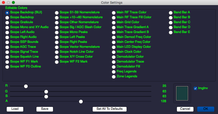

SCP mode
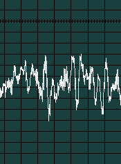
: when on, this changes the scope into a traditional oscilloscope. Ch1 displays the audio waveform (or waveforms, in mode.) Ch2 displays both signal and AGC levels. and affect the Ch2 display. Right-clicking and optionally dragging on the display in the top half will set the Y position of Ch1, while right-clicking and optionally dragging on the display in the bottom half will set the Y position of Ch2. Both and can display signal-level related guides in mode when they are on.
The audio trace (channel 1) runs in positive edge, auto-trigger mode with level set to 50% and sweep rate set to 1:1 by default.
What 1:1 means is that for each audio sample, there is a corresponding point on the scope trace. at 1:2, there is one audio sample and an interpolation between that and the next audio sample. At 2:1, every other audio sample is skipped.
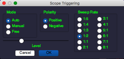
You can control the scope's audio sweep triggering (ch1 only) and timing by accessing the scope control dialog with either →Right-click , or by executing key function 396.
In Auto mode, the scope analyzes a short period of the waveform, locates a transition along the specified edge, positive or negative, within the range of the waveform data it is examining as guided by the level control, and begins the sweep there. In this mode, the scope is guaranteed to trigger constantly, and level is relative to the maximum amplitude of the incoming waveform.
In Manual mode, level sets an absolute value that must be exceeded in the positive or negative direction in the waveform before a sweep will be triggered.
In Free mode, the scope runs with a constant sweep, regardless of the level setting or the polarity of the waveform.
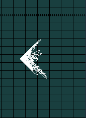
5.18.1.2 - X/Y Mode
X/Y mode
: When on, this changes the scope into an old-school style X/Y tuning scope. In RTTY mode, which is active except in and , you use the two scope knobs to adjust the center frequency and shift widths; if the center frequency is too low (normal range is 850 to 1500 Hz), click to change the range to hi-band, where the range is 1500 to 4750 in 5 Hz steps.
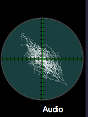
X/Y stereo audio mode
You can also right-click on in order to access gain and Q (X and Y channel bandwidth) controls.
The X/Y scope mode is also useful in tuning other data transmissions such as PSK31 and so on.
In and + modes, the scope serves as a stereo X/Y audio scope, where the horizontal axis deflection represents one channel's content, and the vertical axis represents the other channel's content. In , when , the display will show monophonic deflection (a diagonal line.)
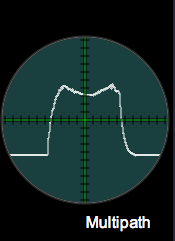
X/Y in FM Multipath mode
Additionally, in mode, an additional click on will activate a multipath tuning mode.
The FM multipath display varies with the amount of direct and reflected (out of phase) signal being received, and can be used to aim FM beam antennas such that the least amount of reflected signal is present, which will in turn almost always increase the fidelity of the signal, except in cases where the direct signal itself is blocked by intervening landscape or man-made structures.
5.18.1.3 - SPE Mode
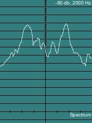
SPE mode
: when on, this changes the scope into an audio spectrum analyzer. , and affect this display. If is off, then the spectrum is automatically set to the demodulator bandwidth. If is on, then you control the bandwidth manually. Use to switch peak hold on and off. Right-click to adjust peak hold time. You can reset the peak waveform by clicking again or turning off and then on again.
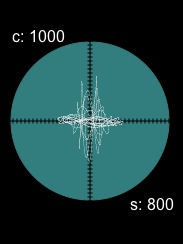
5.18.1.4 - VEC Mode
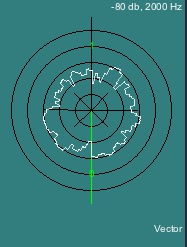
VEC mode
switch: When on this changes the scope into a radial, vector display. , and affect this display. This is basically the same as the mode, except the spectrum is wrapped in a circular manner. However, it is much easier to read, and shows some things — such as overall amplitude — in a more easily comprehensible manner.
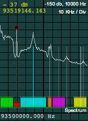
5.18.1.5 - CAR Mode
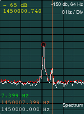
CAR mode
switch: When on, this slowly generates a narrowband (2 Hz to 2 KHz, adjustable with CAR Span) spectrum of the RF carrier frequency. One use for this is to identify AM stations by finely distinguished carrier frequencies. Another is to see at a (somewhat) quick glance just how many carriers are on the frequency you're tuned to. For instance, take a look at the difference between a graveyard frequency and a clear channel. Each vertical division is 10 dB from zero at the top of the scope to a floor of -150 dB at the dark graticule line; each horizontal division is 1/8th of the indicated bandwidth, the center-line is the carrier frequency as displayed in the main demodulator frequency display, to whatever accuracy your SDR is currently operating at. and affect this display. You can shift the center frequency with the lower knob, designated "CAR Shift". Use to switch peak hold on and off. Right-click to adjust peak hold time. You can reset the peak waveform by clicking again or turning off and then on again.
Left clicking (also dragging, if you like) in the scope in mode will set a visible orange marker at the click point on the horizontal axis both as an offset (green readout) and as an absolute (orange readout) frequency. One way this is useful is in the context of looking at AM carrier offsets, something that is interesting to do on the AM "graveyard" channels. When span is set to 128 Hz bandwidth, a +/- 12 Hz margin outside the FCC-mandated 20 Hz frequency accuracy stations are required to comply with is available, so you can see anything that is in compliance, and as far as 60% outside of compliance, or +/- 160% of in-tolerance values of the station's nominal frequency, presuming it isn't a pirate, in which case, it doesn't have one.
CAR, FM signal
spectrum w/markers
In mode, shows a 200 KHz wide spectrum of the entire FM signal. Right-clicking on will turn markers on and off that designate (left-to-right) the baseband monophonic signal, the FM stereo pilot, the center and extent of the FM stereo subcarrier, the center and extent of the auxiliary digital carrier, and the center and extend of both standard SCA channels. Clicking again alternates between the 200 KHz wide view, a narrower spectrum that only goes as far as the digital auxiliary carrier, and a spectrum that shows only the monophonic baseband signal. Right-clicking alternates between no markers, right-side-up markers, and inverted markers.
5.18.1.6 - WTF Mode
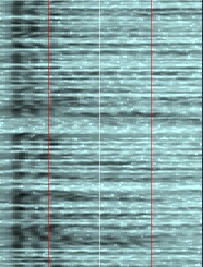
WTF mode
Monochrome palette
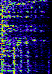
WTF mode
Color palette
switch: When on this changes the scope into a waterfall style audio spectrum display. and affect this display. Waterfall mode is extremely useful for heterodyne location and subsequent notch application. Just left-click on the heterodynes, which will appear as a vertical line. You can use the mouse-roller to fine tune the notch, and the right mouse button to move to another notch (to deal with multiple heterodynes.) You can load a custom palette for the audio waterfall using ; SdrDx will load pal_defaulta.wfp into the audio waterfall on startup if it exists. You can edit the current audio palette with , and you can save it using . When creating palettes for the audio waterfall, I suggest you set the bottom four colors as relatively dark ones, and then the upper three colors as the bright highlights. This accounts for noise levels on SSB well, but may be a little dark for full-quieting AM stations. Any palette you pick here will be a bit of a compromise as signal levels change. Note that the FFT gain will affect how far "up" the palette the audio signal reaches. Experiment!
 Scope WF Outline , Scope WF F1 Mark , and Scope Wf F2 Mark
 5.18.1.7 - 3D Mode
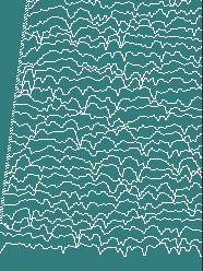
3D mode
 3D: When on this changes the scope into a Z-axis time display audio spectrum; older spectra are further back. , , and affect this display.
You can adjust the waveform amplitude and spacing of the 3D display by right-clicking 3D.
5.18.1.8 - RF/t Mode
RF mode, AM
RF mode, AM trapezoid
With the scope in RF/t mode, when in AM demodulator mode, you can view a reconstructed RF trapezoid; this is not the same as an RF trapezoid measured at the transmitter, because it does not have the original audio available to build the display, but instead must make do with recovered audio. As a result, the trapezoid will always have a perfect shape and cannot measure some of the distortions a transmitter-based measurement would provide for.
You can also measure baseband RF using RF/t (these modes alternate with clocks on RF/t), however again, as you are measuring the RF after it has been frequency-shifted down to baseband (starting at 0 Hz), the display will not look like a traditional RF display at the transmitter, or one taken at a relatively high IF frequency.
5.18.2 - Scope Options
The switch: When on, this changes various spectral displays from a log mode (dB) to a linear one, which can make various frequencies easier to distinguish. Affected modes are , , , and 3D.
The switch: When on, the 3D, , , and displays are smoothed.
The FIX switch: sets the and bandwidths to a fixed setting controlled by the slider to the left. If is not illuminated, 3D, , and bandwidth will track the demodulator bandwidth up to 10 KHz.
switch: This lays an S-Units scale over the ch2 display of AGC and S-Meter signal in mode.
switch: This changes the processing rate for the AGC, S-Meter, and 3D display data.
5.18.3 - Scope Knob Controls
There are two knobs to the left of the scope. In mode, one sets the gain for each scope channel. In , , and 3D modes, if is on, the top knob sets the upper limit of the audio bandwidth to be monitored. The bottom knob sets the system gain for 3D and modes.
The top channel has one trace, which in mode displays the demodulated audio. Sweep rate is adjusted automatically as the sample rate of the various demodulators require. Gain is variable, adjustable with the top knob to the left of the scope. At the lowest gain setting, the trace turns off.
The bottom channel is dual-trace, one white, and one aqua.
The white trace tracks the S-Meter over time, which allows you to perceive QSB as atmospheric conditions change, even when AGC is strongly applied with a large setting of AGC
The aqua trace tracks AGC over time. The higher the AGC level, the more the gain of the signal path is reduced.
Sweep rate is fixed at 3.125 seconds/Div (except if is selected, in which case it is 6.25 seconds/Div), and gain is variable using the top knob of the scope so that the signal can be adjusted to your preference. At the lowest gain setting, these traces turn off.
S1 signal levels are always aligned with the lowest horizontal line in the scope, regardless of the gain setting. If is on, an S-Units scale will be presented on the scope face. This scale tracks the channel gain and adjusts accordingly.
All spectrum modes ( , , , 3D ) allow you to use the left and right clicking/dragging technique to deal with heterodynes.
| toc | index | guide | changes | keyboard | , previous | . next |