Beta Address: http://blish.org/sdrdxdoc/phasing.html
5.13 - Phasing and Noise Reduction
5.13.1 - General
Some SDRs provide for dual antenna inputs. SdrDx can use this facility to provide noise reduction, signal cancellation, or phase-based antenna steering. Each SDR requires individual support of this facility, as the ways the particular SDR implements it is different. Present support includes:
Bandwidth Limits
In dual mode, twice the usual amount of data is being transferred. This limits the upper sample rate available from the SDR to half of normal. For instance, the AFE822 is capable of a 2,000,000 Hz sample rate; and in normal mode, you can expect that. In dual mode, the maximum that will work is 1,000,000 Hz, because there are two full channels (twice as much data) being transferred from the SDR.
To open the Dual Antenna Settings dialog, →Left-click.
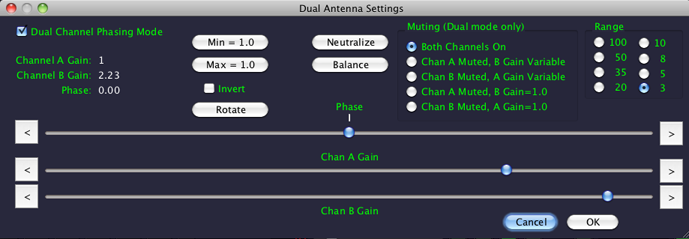
Dual Antenna Settings dialog
5.13.1.1 - Controls
If you →Left-click  Dual Channel Phasing Mode , that will change the phasing mode from one state or the other. If the SDR is running at the time, it will stop, then 2 seconds later, it will restart in the new mode.
When the software and the SDR are in dual channel mode, the  DUL LED indicator on the main panel will illuminate. That way you don't have to open the dialog just to check.
Phase (top slider) adjusts the phase relationship between the channel A signal and the channel B signal plus or minus 180º. This control is only available when Muting is set to
  Both Channels On.
Chan A Gain (middle slider) adjusts the gain of channel A. This control is only available when Muting is set to Both Channels On or Chan B Muted.
Chan B Gain (bottom slider) adjusts the gain of channel B. This control is only available when Muting is set to Both Channels On or Chan A Muted

Settings Report
The  < and > buttons at the ends of each slider allow you to precisely make single-step adjustments. Observe the settings report at the left of the dialog to see the changes.
Invert inverts the SDR's B channel signal. This is the same as a 180º phase shift. One use for it is when using the feature to null out one station, if you change the Invert setting, you will have nulled out the other station, while both inputs work in tandem to receive the originally nulled-out channel. This control is only available when Muting is set to Both Channels On.
changes the state of Invert , and also changes Phase to the corresponding inverted position; this can be used to move a phase setting from near an edge to near the center, or vice-versa. This control is only available when Muting is set to Both Channels On.
Allows you to set Chan A Gain and Chan B Gain to a gain of one, and Phase to zero. This is a good starting point for any manual dual-antenna operation. This control is only available when Muting is set to Both Channels On.
This control initiates an automatic sequence that attempts to analyze the A and B channel signals and set Chan A Gain and Chan B Gain appropriately, along with the lowest Range the gains can be represented in (you can change this to a higher Range if you desire once the analysis is complete.) This feature works best on stable signals; if, during the analysis, the signals are varying in strength, for instance fluttering or fading, you may have better luck with the manual procedure detailed below. Having said that, when signals are relatively stable, you just press , wait, then adjust Phase until you get the desired null. sets the gain of channel A to 1.0, and then sets channel B greater or lesser than channel A as needed to achieve similar signal levels. If the result is the B channel being set to a gain less than one, you can normalize it to 1.0 with →Left-click, described next. This control is only available when Muting is set to Both Channels On.
This control adjusts the two channel gains such that the gain for the lowest gain channel is set to 1.0, and the other channel has a gain higher than one. When choosing this, be mindful of the presence of very strong stations anywhere in the SDR bandwidth; high gains can create very large signals in such cases. This control is only available when Muting is set to Both Channels On.
This control adjusts the two channel gains such that the gain for the highest gain channel is set to 1.0, and the other channel has a gain less than one. This is the conservative choice, as compared to This control is only available when Muting is set to Both Channels On.
to achieve a null, you will often find that the signals eventually change amplitude for various reasons. This reduces the quality of the null. The solution is generally just to press again — the phase will probably remain the same, or very close to it, and the re- will address the level change.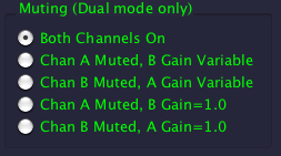
The Muting radio buttons allow you to set the gain of each channel separately for as close to the same S-Meter setting as possible, and spot-check signal strength at each antenna with no gain modification. You can (and should!) observe the S-Meter or the aux scope in mode, with and the aux scope's Ch2 Gain set generously when setting up for a noise reduction or phase-moderated signal discrimination.
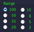
Range radio buttons allow you to set the range of the Chan A Gain and Chan B Gain. When the dialog opens, Range is set to 100 , the maximum. Depending on where you have set the channel gains, some ranges may not be available unless you reduce the channel gain setting(s) that exceed the disabled range(s) maximum capability.
< and > buttons adjacent to the gain sliders less critical. The smaller the difference in signal strength between the two channels, the smaller the range required, as long as you start with neutral controls and proceed as described in the next section, "Nulling out a signal"5.13.1.2 - Nulling out a signal manually
There are two stages to this; initial setup, and adjustment.
Initial Setup:
Open the phasing dialog and if Dual Channel Phasing Mode is unchecked, check it. If the SDR was running, it will stop. You can →Left-click without closing the Dual Antenna Settings dialog, which will restart the SDR in dual-channel mode.
→Left-click. This sets both channel gains to one, and Phase to 0º. Now →Left-click Chan B Muted . This results in reception only from the channel A antenna. Observe the S-Meter. For instance, it may read 20/S9. Now →Left-click Chan A Muted . Adjust Chan B Gain (the bottom slider) so that the S-Meter reads as close to the same value, 20/S9 in this example, as you can get it. Now →Left-click Both Channels On .
Tuning the adjustments:
Step one: adjust Phase (the top slider) until the signal you want to go away reduces in intensity. You can observe this on the spectrum and waterfall, or on the S-Meter, or both. You should also be able to hear the reduction in the undesired signal. Be aware that it may not completely go away at this point, because the gains may not yet be well matched.
ends up out near the left or right edge where this occurs, you can click to bring the adjustment back nearer the center.Step two: Adjust Chan B Gain (the bottom slider) in such a way the reduction in the undesirable signal increases.
Now you begin to repeat the process, and continue doing so until you have achieved the best reduction you can. So go back to step one, and proceed from there.
Once you have achieved the most effective settings, you can compare them with in-phase reception using →Left-click Invert .
Closing the dialog with OK will keep the current settings for extended listening or recording.
Ch A Muted Antenna 1 Mag Loop |
A/B Phased |
Ch B Muted Antenna 2 40 ft. Vertical |
5.13.1.3 - Multipath effects on phasing
Some signals will reach your antennas from more than one direction, a circumstance called "multipath." Because of this, those signals are very likely to present with more than one phase angle. With two antenna inputs, you can only null out one phase angle.
One of the most common sources of multipath for strong local AM stations is reflections off of various man-made and terrain features. Consequently, you may not be able to get as deep a null as you might otherwise expect on some signals.
On the other hand, this can be used to advantage. For instance, if you're listening to a signal, and you are receiving both short- and long-path (you can often infer this from the presence of an "echo"), you can null out the short path signal and listen to the long-path signal, or vice-versa.
5.13.1.4 - Reducing signal jamming
Another very interesting application is reducing or even eliminating jamming. For instance, on the morning of Wednesday, November 30th, 2016, I came across Radio Marti on 5,980.000
The station was being heavily jammed by a signal that consisted of generated noise, centered squarely on the carrier. As this was Radio Marti, the jamming transmission was almost certainly intentional, and coming from with Cuba itself. This suggests that there would almost certainly be a significant phase difference between the station and the jamming emission, because there are two possible sources of phase difference: signal angle, and the distance between two transmissions. Both are likely to be present with a jamming signal. The only cases where you would not be able to successfully null out a jammer is if the phase was the same as the signal being jammed (highly unlikely) or if the phases are changing relatively rapidly so that any one settings does not match the signal phase(s) for long.
In my case, there was a distinct, stable phase difference between Radio Marti and the jammer. Using the phasing dialog, I was able to completely eliminate the noise signal, leaving Radio Marti perfectly in the clear. The phase difference remained stable; I listened for about half an hour without any audible recurrence of the jamming signal. At that point, I opened the phasing dialog again and looked at the A and B channels individually; sure enough, the jamming was still going on.
5.13.1.5 - Other Uses
Local Noise Reduction
For situations where you'd like to get rid of local noise, you want a noise probe. This is typically a low-gain antenna which you place near the noise source. What happens is that because the antenna is low-gain, it doesn't hear the legitimate signals, which are very low level; but because it is very near the noise source, it does hear that. Consequently, the noise can be matched in level and counter-phased against the noise coming in the high-gain antenna, resulting in the ability to remove it without otherwise affecting reception of the desired signal. For this application, antenna spacing is not critical, other than getting the placement of the noise probe actually near the noise.
Directional Steering
Ideally, you'd want two identical high gain antennas with main lobes that are oriented at 90º to one another. Further, if you can see to it that the lobes are exactly north-south for one antenna, and exactly east-west for the other, you will find that with the phasing system gain-neutralized (identical gains for each antenna, typically a gain of one) you can electronically "rotate" your antenna system using Phase such that the slider position in degrees correlates exactly with with compass direction towards the signal when signal is at maximum based on Phase position. For use at HF and below, I highly recommend a pair of RF-PRO-1B active magnetic loop antennas.
5.13.1.6 - I/Q Imbalance Between Channels
When there is any kind of a gain imbalance inherent to a particular SDR, setting the channel gains differently will inevitably create an I/Q spike on one of the channels if you balance it out on the other channel. The solution is to balance the spike once is selected. This way, the total imbalance is addressed, rather than that of just one channel.
| toc | index | guide | changes | keyboard | , previous | . next |