Beta Address: http://blish.org/sdrdxdoc/tuning4.html
5.14 - Demodulator Setup
5.14.1 - Adjusting Bandwidth

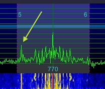
Interfering signal
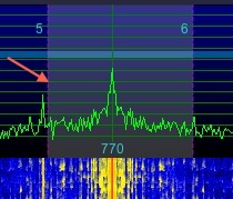
You can adjust either edge of the demodulator's bandwidth by pointing at the left or right edge of the demodulator bar until you see a cursor appear that looks like a tilted, double-headed arrow, then clicking and dragging with either mouse button, or using the mouse roller while you hold the mouse button down.
You can also adjust the demodulator bandwidth by →Left-click , then using the ^ ↑, ^ ↓, ^ → and ^ ← keys on the keyboard. You can remap these function with .
You can also adjust the demodulator bandwidth by clicking one of the bandwidth memories, through ; you can store new values in these memories by either holding Shift while you click the memory, or →Left-click prior to clicking the memory. →Left-click (while it is still blinking) cancels the store operation. Each demodulator mode ( , , etc.) has its own set of seven memories, or in other words, setting the values for does not change the values for or
→Right-click will set the through bandwidth memories to values evenly spaced between and . If is on when you do this, then all bandwidth memories will set ; if it is not on at the time you →Right-click , then all bandwidth memories will set instead.
The LEDs on the bandwidth memories illuminate when the current bandwidth matches that stored in the bandwidth memory. If the settings are identical to those in the memory, the LED will be white: . However, if the bandwidth is the same, but is shifted, then matching memory LED(s) will be red or green
Example:
A memory set to 100:2800 is 2700 Hz bandwidth. So if the demodulator is set to 100:2800, which exactly matches the setting, then .
The same memory will be if the demodulator is set to 150:2850 because this is still 2700 Hz bandwidth, but the bandwidth is shifted up, that is, starts and ends at higher points.
The same memory will be if the demodulator is set to 50:2750 because this is still 2700 Hz bandwidth, but the bandwidth is shifted down, that is, starts and ends at lower points.
With and , the left and right edges adjust together, or symmetrically. With , , , , , and , the left and right edges adjust independently.
5.14.2 - IF Shift
Independent demodulator edge controls are the equivalent of independent left and right IF shift controls with automatic passband compensation on an analog radio.
However, you can also perform an actual IF shift (without passband compensation) in USB, LSB, FSU, FSL, CWU and CWL modes.
To shift up, press ^ Q
To shift down, press ^ V
| toc | index | guide | changes | keyboard | , previous | . next |
 AM
AM